support
contact us

FAQ

If you have any questions on K-WELL's products, please read the FAQ first.If the listed answers still cannot solve your problems, please contract us immediately, we should reply to you as soon as received your request.

Contact us at : sales@kw-magnetics.com or support@kw-magnetics.com

As a dedicated manufacturer of magnetics components and power supplies,K-WELL provides a wide variety of power magnetic, EMC magnetic,external power adapters, battery chargers and open frame power supply unit to meet different demands from the markets. However, selecting the right products relies heavily on the correct electrical characteristics and specification,we listed the Frequently Asked Questions for your reference.

  • Q1How to choosing a switching power supply?
    Ans

    1. To increase the reliability of the SMPS, we suggest users choose a unit that has a rating of 20% more power
    than actual need. For example,if the system needs a 10W source, we suggest that users choose a SMPS with
    12W of output power or more. By doing this,you can effectively boost the reliability of the SMPS in your system.

    2. We also need to consider about ambient temperature of the SMPS and whether there is additional device for
    dissipating the heat. If the SMPS is working in a high temperature environment, we need to make some derating to the  output power.

    3. Choosing functions based on your application:

      Protection function: Over Voltage Protection , Over Temperature Protection ,Over Load Protection , and etc.
     Application function: Signaling Function (Power Good, Power Fail), Remote Control, Remote Sensing, and etc.

      Special function: Power Factor Correction (PFC), Uninterruptible Power Supply (UPS) function.
    4. Make sure that the model qualifies for the safety standards and EMC regulations you need.

  • Q2Why did the power supply shuts down during operation and after turning it off, I can restart the power supply again?
    Ans

    In general there are two circumstances that will cause the power supply to shut down. The first one is the
    activation of the over-load-protection (OLP). To deal with this situation, we suggest increasing the rating of
    the output power or modifying the OLP point. The second one is the activation of over-temperature protection
    (OTP) when the internal temperature reaches the pre-set value. All of these conditions will let the SMPS enter
    protection mode and shut down. After these conditions are removed, the SMPS will be back to normal.

  • Q3What is "Inrush Current"? What will we notice?
    Ans

    At input side, there will be (1/2 ~1 cycle, ex. 1/120 ~ 1/60 seconds for 60 Hz AC source) large pulse current
    (20~100A based on the design of S.P.S.)at the moment of power on and then back to normal rating. This
    "Inrush Current" will appear every time you turn on the power. Although it will not damage the power supply,
    we suggest not turning the power supply ON/OFF very quickly within a short time. Besides, if there are several power suppliesturning on at the same time, the dispatching system of AC source may shut off and go into protection mode because of the huge inrush current. It is suggested that these power supplies start up one by one or use the remote control function of SMPS to turn them on/of.

  • Q4What is PFC?
    Ans

    Power Factor Correction or PFC is to improve the ratio of apparent power to real power. The power factor is
    around 0.4~0.6 in non-PFC models.In models with PFC circuit, the power factor can reach above 0.95. The
    calculation formulas are as follows: Apparent Power=Input Voltage x Input Current (VA), Real Power=
    Input Voltage x Input Current x Power Factor (W).From the point of view of environment friendly, the power plant
    needs to generate a power which is higher than apparent power in order to steadily provide electricity. The real
    usage of electricity is defined by real power. Assuming the power factor is 0.5, the power plant needs to produce
    more than 2WVA to satisfy 1W real power usage. On the contrary, if the power factor is 0.95, the power plant only
    needs to generate more than 1.06VA to provide 1W real power, It will be more effective in energy saving with PFC
    function.Active PFC topologies can be divided into single-stage active PFC and two-stage active PFC, the differenceis show as in the table below.

    FC topologyAdvantageDisadvantageLimitation
     Single-stage
     active PFC
     Low cost
     Simple schematic
     High efficiency in 
     small 
     watt application
     Huge Ripple
     complex feedback 
     control
     1.Zero “hold up time”. The output is
        affected by the AC input directly.
     2.Huge ripple current results in lower LED life
        cycle.(drive the LED directly)
     3.Low dynamic responds, easily affected by
        load.
     Two-stage active
     PFC
     High efficiency
     Higher PF
     Easy feedback control
     High adoptive against 
     load condition
     Higher cost
     Complex schematic
     Suitable for all kinds use


  • Q5What is the difference between -V and COM which are marked on the output side?
    Ans

    COM (COMMON) means common ground. Please see below:
    Single output: Positive pole (+V), Negative pole (-V)
    Multiple output (Common ground): Positive pole (+V1, +V2), Negative pole (COM)


  • Q6What is power good and power fail signals and how can use it?
    Ans

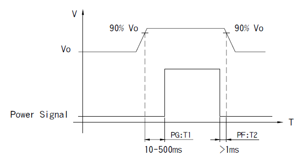
    Some power supplies provide a "Power Good" signal when they are turned on, and send out a " Power Fail"
    signal when they are turned off. This is usually used for monitoring and controlling purpose.

    Power Good: after the output of a power supply reaches 90% rated voltage, an TTL signal (about 5V) will be
    sent out within the next 10-500ms.

    Power Fail: before the output of a power supply is less than 90% rated voltage, the power-good signal will be
    turned off at least 1ms in advance.
    Q11 -1.png

  • Q7What are the protection forms of overload/overcurrent?
    Ans

    When current drawn exceeds the rating of the PSU, the protection circuit will be triggered to protect the unit
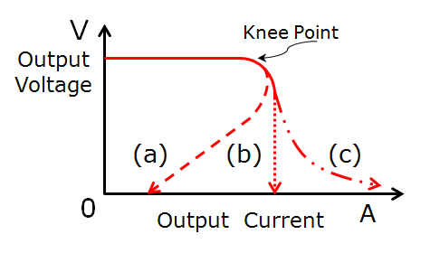
    against overload/overcurrent. Protections of overload/overcurrent can be divided into several forms:
    (1)FOLDBACK CURRENT LIMITING
    Output current decreases about 20% of rated current, shown as curve (a) in the figure below.
    (2)CONSTANT CURRENT LIMITING
    Output current remains at a constant level and within the specified range while the output voltage drops to
    a lower level, shown as curve (b) in the figure below.
    (3)OVER POWER LIMITING
    Output power remains constant. As output load increases, output voltage decreases in proportion, shown as
    curve (c) in the figure below. 
    (4)HICCUP CURRENT LIMITING
    Output voltage and current keep pulsing ON and OFF repeatedly when protection is activated. The unit
    automatically recovers when faulty condition is removed.
    (5)SHUT OFF
    Output voltage and current are cut off when output load reaches protection range.
    NOTE: Protection mode of some of the products combines with different types of the forms mentioned,
    such as constant current limiting + shut down.
    Q13-1.png
    Recover method:
    (1)Auto Recovery: PSU recovers automatically after faulty condition is removed.
    (2)Re-power on: PSU restarts by manual AC re-power on after faulty condition is removed.
    Note:Please do not operate PSU in overcurrent or short-circuit condition for a long period of time to prevent
    a shorten lifespan or damaging the PSU.


  • Q8What is Ripple & Noise? How to measure it?
    Ans

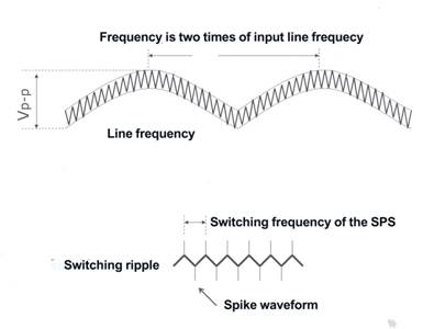
    It is the small unwanted residual periodic variation of the direct current (DC) output of a power supply which has
    been derived from an alternating current (AC) source. The wave form is shown as figure below.
    Q14-1.png

    There are two AC contents, also known as Ripple and Noise (R&N), on the DC output. The first one, coming from
    sine wave rectification, is at a low frequency which is 2 times of the input frequency; the second one is at high
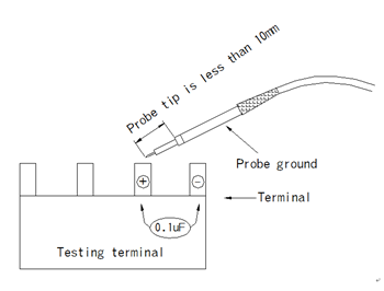
    frequency which is from the switching frequency. For measuring high frequency noise, configurations of an oscilloscope with a bandwidth of 20MHz, a scope probe with shortest ground wire possible, and add 0.1uF and 47uF capacitors in parallel with test point for filtering out noise interference are requires to be made.
    Q14-2_副本.png

  • Q9What is Withstand Voltage?How to measure it?
    Ans

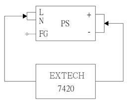
    Indicates Hi-Pot Test or Electric Strength Test. The input should be shorted together as well as the output before
    test. The test will proceed under particular loop, such as I/P-O/P, I/P-FG and O/P-FG with certain high voltage
    value for 1 minute. (The typical leakage current is 25mA when testing with AC)

    Q15-1_副本.jpg
    1.Hi-Pot Test is a way to ensure if the isolation between primary to secondary is done properly, preventing
    damaging to SMPS. when facing high voltage between input and output. The test voltage should be gradually
    increased from 0V to preset level and remains at preset level for 60 seconds with raise time greater than 1
    second. In mass production, the test period could be reduced to 1 second. If the leakage current flowing
    through the isolation material increases rapidly when applying test voltage,it indicates ineffectiveness of
    isolation (dielectricbreakdown).Corona effect/discharge or transient electrical arc is not considered as failure.

    2.When AC test voltage is applied, Y capacitors are the main cause of leakage current. A 4.7nF capacitor can cause leakage current of 5mA. According to regulations of UL-554, the Y capacitors should be removed for
    Hi-Pot test, which is not practical for mass production. The only solution is to increase the leakage current
    setting, typically 25mA, of test instrument. Presently, the criteria of leakage current are not defined in safety regulations.

    3.According to regulations of IEC60950-1, DC test voltage can be substituted when there are bridging capacitors coupled between primary and econdary circuits, so as to solve the problem of leakage current.


  • Q10How to find products you need in K-WELL website?
    Ans
    1.Click “Products” on the website Menu. In products menu you can find two kinds products of power supply
    and magnetic componets.then you can choose you needs that enter the corresponding page. our part number
    rule :The English letter → indicates the product category,The number → indicates power range (power supply)
    or dimension(magnetic components).
    2.You can download the product selection guide from our data download center and compare the product series
    Numbers with your requirements.
    3.You can quickly search in our fast search bar by entering the product serial number.


< 1 2 >